Monday, April 16, 2012

Try again

OK, I found a roundabout way to load the photos.  

Here is the engine cowling sheet metal.   Although for the most part the engines are exposed there is an engine mount with provisions to hold the oil reservoir and radiator.  This is the radiator fairing.


Here it is with the radiator mounted.


These parts and all of the control surfaces have been primed.

Chris, Frank, and I worked this weekend on assembling the fuel tanks.  This is a riveted structure and has 8802 sulfide sealant applied at all exterior mating surfaces.


I still have some work to do on the first tank.

That's all for now.

I'm Back

Sorry for the lack of postings these last few months.  Some of it was laziness, some was due to a diversion from the Aircam.

Anyway, a lot of progress has been made.  Almost all of the parts have now been primed.

Well you'll just have to trust me on this.  I seem to be having trouble uploading pictures.  I'll work on it and get back with you.

Sunday, December 4, 2011

Such A Slacker

I have been working on the Aircam but I have been remiss in updating the blog.

I have been working the elevators.  They are drilled out now and will need the usual disassembly/deburring/alodine and prime.

Here is the trim motor that sits inside the left elevator.  I will drill the ribs to attach this later.


The plans did not originally have this reinforcing gusset.  It has a late P/N and is only shown as an add on to the assembly.  It is simple to install and stiffens up the elevator horn area.  There is one on the top and bottom.

Here is the trim tab being drilled for the four hinges.  The trim tab is only on the left hand elevator.


This is the trim tab horn.

 Here the motor has been drilled in though you can't see that in this picture.


These are the two elevators sitting on top of each other.

I did double the number of rivets that will hold the right hand trailing edge onto the rear spar.  My trim tab skins seemed a little puckered to me and this will lay that skin down tighter.


On to the rudder.  Here are the main structural parts.


I should have it completed this week.  Then it will be time for a weeks worth of deburring.

Tuesday, November 8, 2011

I'm Back

October was a busy month but not so much for building the Aircam.  first there was a wedding, then landscaping, then final prep for the annual Hood Field fly-in.  Although we did have 150 or so people for that there was no actual flying due to weather.

Meanwhile progress has been made.  The vertical fin has been dis-assembled and work on the horizontal stabilizers begun.

Also, the center section has started to come apart.


Had to roll the Aircam out of the shop for shop clean up.  Here it is in the nice bright sun.  It was not like this on the day of the party.


Even got official airport vehicle flags to help marshall arriving aircraft.  Maybe I'll get to use it next year.


So back to the vertical stabilizer.  The is the bearing bracket on the rear spar that will support the elevator.


This is the bracket for the top rubber bearing.


Bracket for the brace wires, one for the front and the rear.


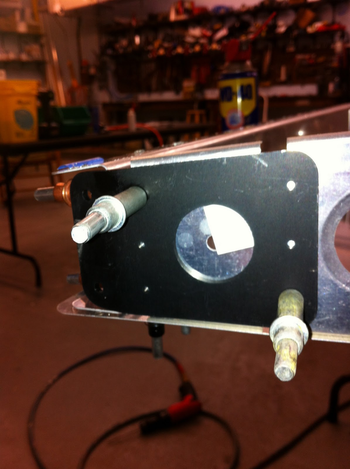
This bracket will support the horizontal stabilizer.


The cadmium plated insert is threaded on both ends to accept a clevis.  There is only one insert, the image shows a reflection.


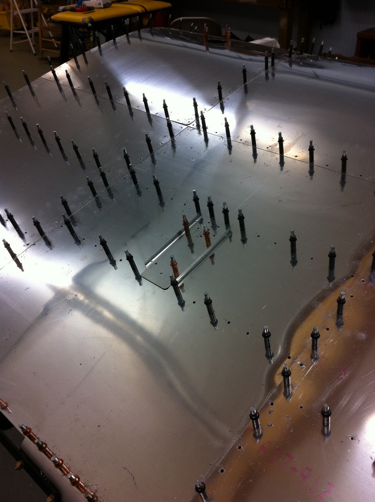
Now on to the horizontal stabilizer. This is an all aluminum structure that will be fabric covered.  Here are a few details shots.


Here it is on a flat surface to check squareness prior to drilling the diagonals in place.


These drag - antidrag wires are pre-made.  You attach them and check squareness.  You adjust by twisting the wire as needed.  This one was ood to go as is.


I needed some supports for the stabilizer so the clecos would clear the surface.  We went down to Don's hangar and got some left over 4 inch square tubing used for his framework.  There were two black widow spiders in one of the pieces.  She had a body the size of a marble.

Aviation can be dangerous!

Congratulations to my friend Chris.  He got his RV-10 inspected this past weekend by the FAA representative.  He found no gripes.  First flight is as soon as he gets the fairings back on.  Also Happy Birthday Chris!!

Tuesday, October 4, 2011

Going Backwards

Reached the point where it is time to take the center section down and the vertical stabilizer off.  The always seems like going backwards.

Here is a shot of the tool I made so that I could accurately drill the additional holes in the rear spar of the center section.  it worked great.


You can see one of the extra holes on the left side of this picture.  I had to drill about 60 extra holes on the top and the bottom.


Back on to the fuel tanks.  I had to rivet the nutplates on the sending unit access panel:


Saturday morning I went over to a fly-in at Pink Hill.  There was an abandoned KR-2 project in one of the hangars with this logo:

I always heard KR-2s were pigs!

So we took the center section off.


And the vertical fin needs a little work such as the tip cap:


These are the center section access panel doublers.  There are 12 nutplates on each of these, there are three.  This drilling took over an hour with the deburring and countersinking.  They will be alodined and primed before attaching the nutplates.


And here is the ELT antenna doubler being drilled.  It will eventually go underneath the skin.  Again it has to be primed before permanent attachment.

Sunday, September 25, 2011

What's All The Flap About?

Finished the flaps today.  As promised I took a few detail shots to show how it all goes together.

The flap ribs are just 1/2 inch diameter thin wall aluminum tubing.  They are inserted into a pre-cut hole in the spar and are secured from moving around by a plastic plug that is riveted from the front of the spar.    In this picture I have laid out the main parts plus a tool used to hold the plastic plug in place while it is riveted.  the spar shows the 1/2 inch hole opening and you can see the hole in the front of the spar for the rivet.  Below the spar are the plastic plug, aluminum tube that is the rib, and another piece of tubing that will fit inside the aluminum tube to hold the river against the ID of the 2 inch diameter spar.


Here I have the rivet inserted into the hollow plug with the inner tube sticking through the rib tube.  The rivet is actualy inserted from the outside of the spar.


Here it is ready for riveting.  I can now press the aluminum tube and the inner tube hard against the ID of the spar while I set the rivet.


Here looking through the 1/2 inch hole in the spar you can see the plug is riveted and will stabilize the rib tube from sliding around.


And a shot of the tube sticking out of the spar prior to installing the trailling edge which kas a similar plastic plug on its outside.


Here the flaps are finished.  The blue tape secures the trailing edge while I attached the root ribs.  Eventually these will be covered with Poly Fiber and that tension in the fabric will hold the trailing edge on.  The root ribs are fairly conventional and are riveted onto the spar and trailing edge.


Time to move back to the fuel tanks.  I thought my friend Dennis was going to come over today but I never checked on his status this week.  Its a good thing he didn't show because I was not quite ready.  I did find enough parts to assemble the rear inspection panel and install one of the fuel sending units .  I had to install some anchor nuts for this.  Some of them twice since I put the wrong size on first.


I didn't get much done last week as I had to tend to Mom's hot water heater.  All is fine there now.  I did receive my tooling so I can press on with the center section drilling this week.  More on that later.

Sunday, September 18, 2011

Laissez Les Bon Temps Rouler!!

In order to Let The Good Times Roll in an airplane you have to have ailerons, so while I'm waiting on some #20 reamers to finish the center sectionI decided to move on to the aileron frames.  By the way,I used  up all 250 clecos I ordered the other day and will need some more for the spar of the center section.  All of the copper colored ones in this picture will be black.  The bottom of the spar is the same.  About 100 in all.


The aileron frames consist of a large diameter front spar, a small diameter trailing edge and some tubes for ribs.  No real airfoil section just the taper.  First off you have to install the nutplates for the hinges.  These are close spaced 1/4 inch diameter nutplates and they are a pain to install due to the closeness of the river to the thread.  The sheet metal doubler has to be laid out as well but is easy to rivet.


The leading edge spar has a smaller tube riveted inside to form the outboard end.  Here it is inserted into the larger tube.


The large holes you see below will receive the tubes that are the ribs.  They really just act as compression members.

A detail of the nutplate prior to drilling.


And one of the sheet doubler prior to marking it and drilling.  I put extra washer under the head so I don't have to engage all od the self locking thread of the nutplate to hold it for drilling.  They will not be used in the end.


Another view of the tube extension.


The sheet doubler after it has been drilled but not riveted.


Here the extension has had the four large pull rivets installed.


In order to rivet the nutplate I have to install small diameter collars on the stem so the nose of the rivet gun clears the threaded boss.


Once these are done you have to install plastic nipples that will locate the ends of the tubes.  The ones on the leading edge are inside the spar and are not visible.  Here is one on the trailing edge.  They are held on by a large rivet.


The thin looking tubes on the table are the trailing edges.  Once you have installed all of the keepers you simply put the tubes in place and hold it together with tape until you can attach the root rib and outboard end fastener.  I don't have any pictures of that tonight.  I will get some this week and upload them.


I did mage to finish both ailerons this weekend.  Tmac had come over Saturday to help.  Here he is holding a completes frame.


These control surfaces will be covered using the PolyFiber process which uses a heat shrunk dacron Which will hold everything together.

This week I hope to get the flaps done.  They are the same construction except they have a sheet metal rib on both ends and no taper.